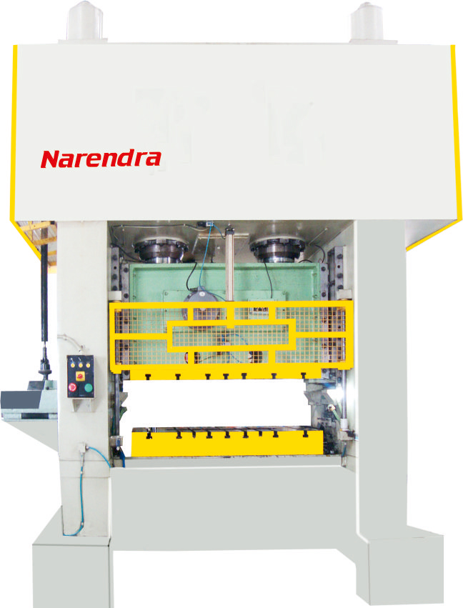
Two Point High Speed Press (NHP)
FRAME
Welded steel construction, stress relived, computer aided frame design, extreme rigidity with uniform parallel deflection, ideal for progressive tooling, ensure high speed laminating precision and rigidity
SLIDE
The slide is guided accurately throughout the whole stroke with high precision eight way bearing guides free from backlash. Eight point, square corner gibbing provides long parallel guiding surface that maintain slide parallelism under off centre load resulting high precision & long tooling life
CRANK SHAFT
It is made from a forged piece of carbon alloy steel. Shaft is ground finished on bearing surface. All main bearing are of heavy walled nickel phosphorous and bronze.
DYNAMIC BALANCING
Provides better precision quality of lamination and longer life by controlling the thursh and vibration in the frame generated by crank shaft rotation.
PLUNGER GUIDE
The rotation of eccentric shafts creates front & back loads that changes guides clearance this is controlled by plunger guided design this eliminates change in guide clearance resulting high precision.
HYDRAULIC SLIDE ADJUSTMENT LOCKING DEVICE
This eliminates clearances inside the slide adjustment assembly. Maintain accuracy of slide travel at bottom dead centre.
STICK RELEASE DEVICE
Resolves tool jam problem, easy to operate
LUBRICATION
Motorised forced feed lubrication is of re–circulating type ensures adequate oil supply,depending upon the bearing area ensures cooling of bearing as well as any fault in the system with cause instant stopping of the press and will be shown optically on control pannel.
NHP-200
STANDARD FEATURES
- VARIABLE SPEED FREQUENCY DRIVE
- RE–CIRCULATING MOTORISED LUBRICATION SYSTEM
- DUAL SOLENOID VALVE
- 8 POINT GIBING
- SHUT HEIGHT INDICATOR
- SLIDE ADJUSTMENT MOTORISED
- HYDRAULIC THREAD LOCKING
- CONTROL THROUGH P.L.C
- GUIDEWAYS BEARING ALONG WITH BEARING HOLDING BRACKET
- SLIDE COUNTER WEIGHT
- HYDRAULIC STICK RELEASE
OPTIONAL ACCESSORIES
- ANTI–VIBRATION MOUNT
- DIE LIFTER
- DIE CLAMPER
- DIE ARM
- FLYWHEEL BRAKE
- STRAIGHTNER WITH S–LOOP
- CHANGE GEAR TYPE CAM INDEX ROLL FEED
- AIR INJECTOR
Technical Specifications
MODEL |
NHP–60 | NHP–100 | NHP–125 | NHP–160 | NHP–200 | NHP–250 | |
|---|---|---|---|---|---|---|---|
CAPACITY |
TON | 60 | 100 | 125 | 160 | 200 | 250 |
CAPACITY AT 20° BEFORE BDC |
MM | 3.2 | 3.2 | 3.2 | 3.2 | 3.2 | 3.2 |
STROKE FIXED |
MM | 30 | 30 | 30 | 30 | 30 | 40 |
SPEED VARIABLE |
MIN(SPM) | 100 | 100 | 80 | 80 | 80 | 80 |
MAX(SPM) |
300 | 300 | 250 | 225 | 200 | 200 | |
SHUT HEIGHT |
MM | 340 | 360 | 390 | 400 | 400 | 400 |
SLIDE ADJUSTMENT |
MM | 40 | 40 | 40 | 50 | 50 | 80 |
BLOSTER AREA(LR X FB) |
MM | 850 X 630 | 1100 X 700 | 1300 X 800 | 1600 X 800 | 1800 X 900 | 1800 X 1000 |
SLIDE AREA (LR X FB) |
MM | 790 X 450 | 1000 X 500 | 1200 X 600 | 1500 X 700 | 1700 X 700 | 1700 X 900 |
TABLE OPENING (LR X FB) |
MM | 710 X 200 | 900 X 200 | 1100 X 210 | 1300 X 250 | 1500 X 350 | 1550 X 350 |
OPENING IN BOLSTER |
MM | AS REQUIRED | |||||
OPENING IN UPRIGHTS (FB X HT) |
MM | 300 X 300 | 350 X 350 | 400 X 400 | 450 X 450 | 450 X 450 | 450 X 450 |
BOLSTER THICKNESS |
MM | 115 | 140 | 150 | 160 | 180 | 180 |
HEIGHT OF TABLE FROM FLOOR |
MM | 900 | 1000 | 1000 | 1000 | 1000 | 1150 |
MAIN MOTOR POWER |
HP | 10 | 20 | 25 | 30 | 40 | 40 |
AIR SUPPLY BAR |
kg/cm2 | 5.5 | 5.5 | 5.5 | 5.5 | 5.5 | 5.5 |